内页banner
  • The initialization process after the RAID is configured The initialization process after the RAID is configured Oct 12, 2023
    For parity RAID, after the RAID parameters are set on the RAID card and the RAID Settings are applied, all the disks in the RAID array need to be initialized. The time required is related to the number and size of the disks. The larger the disk, the more there are, and the longer it will take. Consider: What does a RAID card write to disk? You can think about a new disk just out of the factory, is there any data on it? Yes. What data? It's either all zeros or all ones. Here, all zeros refer to the actual data part, except for some special positions such as sector headers. Because the magnetic region on the disk has two states, either the n-pole or the S-pole. So that means it's either 0 or 1, and there can't be a third state. So what about these 0's or 1's? Of course, these magnetic regions don't have a chaotic state between 0 and 1. If we do RAID5 with a few disks, but do not change any data on the disks, let's see what state we will be in at this point, say 5 disks, 4 data disk space, 1 parity disk space, on the same strip, 4 data blocks, 1 parity block, and all the data on the blocks are all 0, then if we calculate RAID5, It's true, because 0 XOR 0 XOR 0 XOR 0 XOR 0 XOR 0=0, right. If you start with all 1's, then similarly 1 XOR 1 XOR 1 XOR 1 XOR 1 XOR 1=1, also true. However, if RAID5 is made of 6 disks, and the initial values are all 1, the situation is contradictory. 1 XOR 1 XOR 1 XOR 1 XOR 1 XOR 1 XOR 1 =0, in which case the correct result would be that the parity block is 0, but the initial disk is all 1, and the parity block data is also 1, which contradicts the calculation. If the initialization process doesn't make any changes to disk and we just write data, for example, we write a piece of data to the second extend, changing 1 to 0, and then the controller validates the data according to the formula: parity data for new data = (old data EOR new data) EOR. (1EOR 0) EOR1=0, and the new parity is 0, so the final data looks like this: 1 XOR 0 XOR 1 XOR 1 XOR 1 XOR 1. We figured it out to be equal to 1, but the RAID controller figured it out to be 0, so there's a contradiction. Why did you make this mistake? That's because the RAID controller didn't start with a proper data relationship in the first place, and the parity data of the parity block was inconsistent with the data block at the beginning, which led to more and more errors. So after the RAID controller is set up and enabled, in the process of initialization, it needs to write 0 or 1 for each sector of the disk, and then calculate the correct parity bit, or do not change the data of the data block, directly use these existing data, recalc the parity block data of all strips. On this basis, new incoming data will not be misrepresented. Tip: For products such as NetApp, RAID groups do not need to be initialized and are available immediately. Even adding disks to a RAID group that already has data does not cause any additional IO. Because it will reset all Spare disks, that is, send a Zero Unit SCSI instruction to the disk, and the disk will automatically perform the zero. For RAID groups made from these disks, there is no validation and therefore no initialization, or waiting for the disks to clear to zero.   Unleash the power of data! Classic reliability, innovative evolution - RAID Card brings you beyond imagination performance and reliability. Whether you are an individual user, an enterprise, or a data center, our RAID cards will provide you with unparalleled data protection and high-speed transfer. STOR Technology Limited provides original and new cloud storage products, such as megaraid sas 9341 8i, lsi 9361 8i 2gb, lsi megaraid 9460 8i, etc., welcome to consult.
  • ROC technology and memory on RAID cards ROC technology and memory on RAID cards Sep 27, 2023
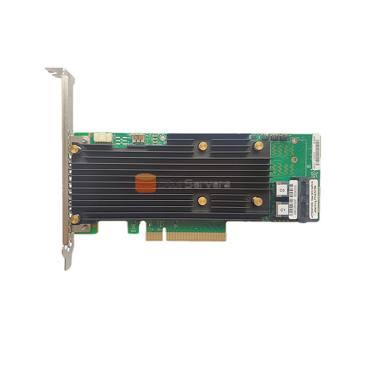
    This time let's talk about ROC technology and memory on RAID cards. RAID On Chip (ROC) technology ROC technology is a kind of cheap RAID technology which is put forward by Adaptec company. It uses the CPU processing chip in the SCSI card and realizes by adding RAID code into the ROM of the SCSI card. In 2001, Adaptec demonstrated its iROC technology, and in 2003 it was launched as HOStRAID. iROc is RAID on Chip, essentially is to use the RISC processor inside the SCSI control chip to complete some simple RAID types (RAID0, 1, 0+1). Because RAID0, 1 and 0+1 need small amount of computation, they can also be realized by using RISC processor in SCSI controller. With ROM code, RAID0, 1, or 0+1 implemented by iROC has boot capability and can support hot backup. In entry-level tower servers and 1U rack-mounted servers, SCSI control chips are often integrated on the motherboard, but stand-alone RAID cards are not standard. The starting point of iROC is to provide these systems with basic hardware data protection, and to purchase standalone RAID cards when more complex RAID5 is required. The emergence of iROC adds a simple option to the data protection scheme of low-end server products. The main disadvantage of iROC or HOStRAID is the poor operating system compatibility and performance, because there is no special RAID computing processor, so using this configuration of RAID will reduce the performance of the server system to a certain extent, and it only supports RAID 0, 1, 0+1, can only support a few SCSI disk RAID. Compared with IDERAID0, 1, and 0+1, the HOStRAID technology has similar features at a much higher cost. In addition, the Hostraid technology is bound to face competition at the lower end from the newer and better performance S-ATARAID. Memory on a RAID card The memory on the RAID card has two functions: data cache and code execution memory. RAM is required to execute the code on the CPU of the RAID card. If the code is read directly from ROM, the speed will be greatly affected. Therefore, the RAM of the RAID card has a fixed address segment for storing the code executed by the CPU. Most of this space is used for the data cache described below. Caching, or buffer memory, is all that is needed to buffer between the two sides of the communication. We know that between CPU and memory is L2Cache, which is higher than memory RAM speed, but not as high as CPU speed. Similarly, a cache is required between the RAID controller and the disk channel controller to fit in, because the RAID controller can process much faster than the channel controller can collect data outgoing from the connected disks on the channel. This cache does not need to use a high-speed circuit like L2Cache, and RAM is sufficient. RAM is fast enough for both. In addition to accommodating chip communication at different rates, cache RAM also serves to buffer data. For example, if the upper layer makes a 10 request, the RAID controller can queue the request in the cache and execute it one by one, or optimize the IO, merge one by one, and concurrency one by one. Experience unparalleled performance - industry-leading RAID cards from a team of professionals with over 10 years of experience. Discover the precision of original high performance products and services! A large number of raid cards can be provided, such as: megaraid 9341, lsi 9361 8i raid controller 05-25420-08, RAID 940-32i 4y37a09733, etc. Welcome to consult.
  • RAID card initialization and configuration process,0 channel RAID card,No drive raid card RAID card initialization and configuration process,0 channel RAID card,No drive raid card Sep 15, 2023
    Today we will talk about the initialization and configuration process of RAID cards as well as 0-channel RAID cards and driderless Raid cards RAID card initialization and configuration process The so-called initialization is to say that after the system is powered on, the CPU executes the first instruction on the specific address of the system bus, which is the address of the motherboard BIOS chip. The BIOS chip contains the first instructions for the CPU to execute, and the CPU executes them one by one until, at a certain point, an instruction tells the CPU to address the ROM addresses of other devices on the bus (if any). That is to say, after the system is powered on, the CPU will always execute the program code in the ROM of the SCSI card on the device to initialize the card. Initialization involves checking the card model, manufacturer, and scanning all SCSI buses on the card to identify each device and display it on the display. In the process of initialization, you can enter the BIOS of the SCSI card itself as the motherboard BIOS setting, setting content including check each connected to the SCSI bus device capacity, manufacturer, status, SCSIID and LUNID and so on. 0 channel RAID card A 0-channel RAID card is also called a RAID child card. 0-channel means that there is no SCSI channel in the backend of the card. After the child card is inserted into the PCI slot of the host, it can use the SCSI cards already integrated on the motherboard or already plugged into the PCI to control their channels, so as to realize RAID. This 0-channel child card is also inserted into a PCI card, but it needs to use the motherboard for 0-channel child card specially designed logic circuit, external and SCSI controller to form a RAID card to use, but this card is physically divided into two PCI slots. On a specific PCI slot on the motherboard, there is an ICR logic circuit that intercepts the address signals sent by the CPU and the interrupt signals sent to the CPU. CPU sent here originally used to control the SCSI controller address signals, are now all redirected by the ICR circuit to RAID daughter card, including the motherboard BIOS initial loading ROM, is not loaded into the SCSI card ROM, but into the RAID daughter card ROM. RAID cards completely replaced SCSI cards for the host system. The communication between RAID card and SCSI controller, including address information and data information, needs to occupy the PCI bus, which causes some performance loss. Communication between RAID daughter cards and SCSI cards is not redirected by ICR circuits. No Drive Raid card PhotoFast has designed a Riad card that is quite innovative. The traditional Raid card uses PCIX or PCIE bus to connect to the computer, but the PhotoFast Raid card uses SATA interface to connect to the computer, that is, the Raid card connects multiple physical disks into a number of virtual disks. And connect these disks to the computer through the SATA interface, and the computer thinks that it is connected to multiple SATA physical disks. This way, the Raid card can be used by most operating systems without any driver (most operating systems come with a SATA controller driver). If you have any questions, please consult and answer them at any time. STOR Technology Limited also offers a wide range of original high-performance products, such as megaraid sas 9341 8i, lsi 9361 8i 2gb, lsi megaraid 9460 8i, and more.

Need Help? leave a message

leave a message
If you are interested in our products and want to know more details, please leave a message here, we will reply you as soon as we can.
Submit
Contact us #
+86-755-83677183

Our hours

Mon 11/21 - Wed 11/23: 9 AM - 8 PM
Thu 11/24: closed - Happy Thanksgiving!
Fri 11/25: 8 AM - 10 PM
Sat 11/26 - Sun 11/27: 10 AM - 9 PM
(all hours are Eastern Time)

Home

Products

whatsApp

contact